Disconnect before changes
Remove USB cables before modifying a circuit. Double-check every connection before restoring power.
Embedded Linux · Course kit documentation
A clear, interactive guide to the hardware in your kit—what each component does, how to connect it, and how to keep it safe.
Read before connecting power
Small wiring mistakes can damage the electronics—or the computer connected to them.
Remove USB cables before modifying a circuit. Double-check every connection before restoring power.
Every exercise uses only the supplied materials and course prerequisites. Do not cut wires or solder components.
Remove surplus materials, run a full inventory check, and tell the teacher about anything defective or missing.
Course kit contents
Check each item as you verify it. Your progress is saved in this browser.
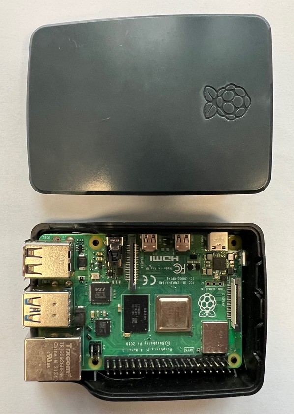
Keep it in the bottom part of its enclosure. Enclosure color may vary.
1 unit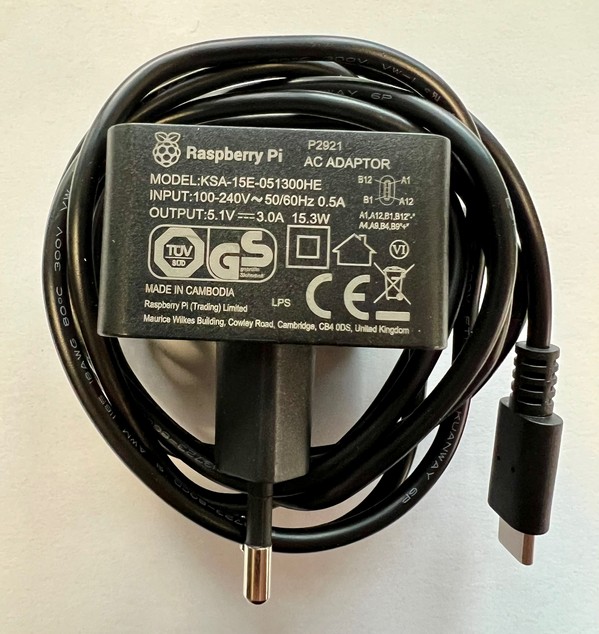
Power supply for the Raspberry Pi 4.
1 unit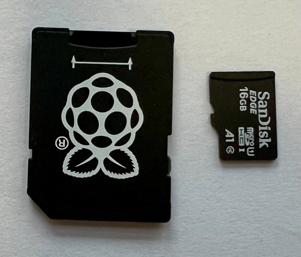
Card brand may vary across kits.
1 set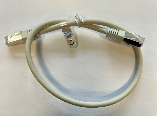
Brand may vary across kits.
1 cable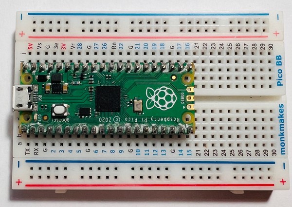
Mounted on a breadboard. Do not remove it.
1 board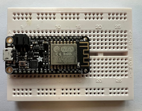
Mounted on a breadboard. Do not remove it.
1 board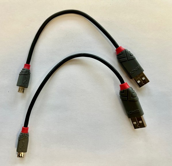
Cable brand may vary across kits.
2 cables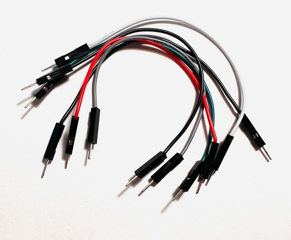
Used to build breadboard circuits. Exact quantity is not tracked.
Assorted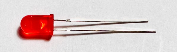
Use each in series with a 220 Ω resistor.
2 units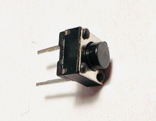
Pressing the button short-circuits its two pins.
1 unit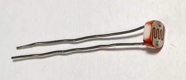
Use in series with a 1 kΩ resistor.
1 unit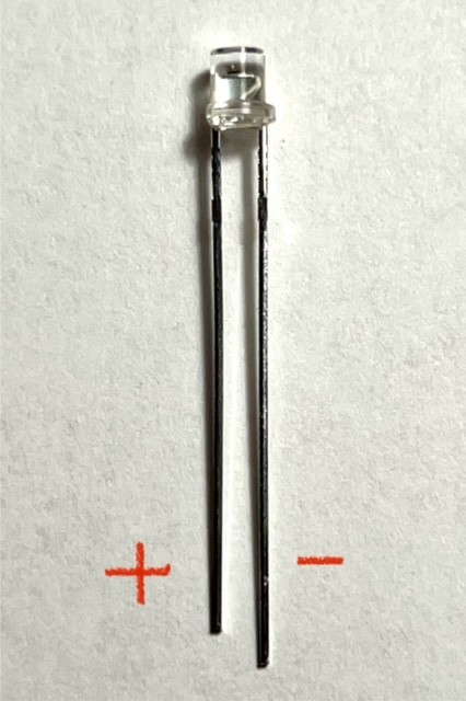
Use in series with a 10 kΩ resistor.
1 unit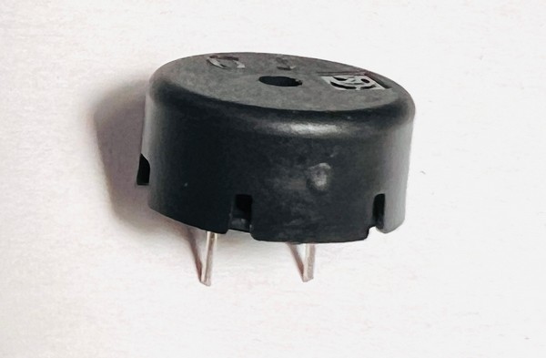
A “+” mark may identify the positive pin.
1 unit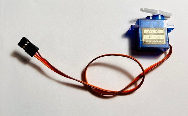
Orange: signal · Red: +5 V · Brown: GND.
1 unit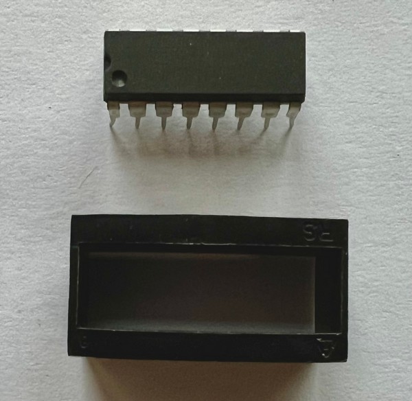
Analog-to-digital converter.
1 unit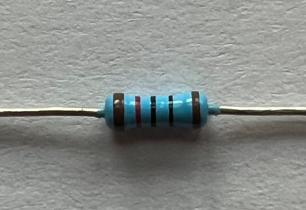
2 × 220 Ω (red-red-black-black-brown) and 1 × 10 kΩ (brown-black-black-red-brown).
3 unitsConnection essentials
These details are easy to overlook. Verify them before power is applied.
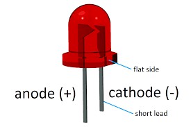
The longest pin is positive (+). The flat side is closest to the negative (−) pin.
Series resistor: 220 ΩThe shortest pin is positive (+)—the opposite of the red LED convention.
Series resistor: 10 kΩConnect orange to a GPIO signal, red to 5 V, and brown to GND.
Signal series resistor: 10 kΩCore hardware
The kit’s embedded Linux computer. Open the enclosure by gently pressing the two triangle symbols while lifting the lid. Do not remove the Pi from the enclosure base.
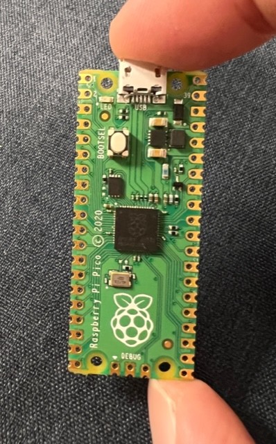
A microcontroller mounted on a breadboard for real-time input/output exercises. Leave it attached to the breadboard.
Based on the ESP8266 microcontroller. Its Wi-Fi radio supports 2.4 GHz only; the Arduino ESP8266 library supports WPA and WPA2, but not WPA3. Leave it attached to the breadboard.
Circuit building
The highlighted lines show which pinholes are electrically connected. They let you assemble experimental circuits without soldering.
Keep both microcontrollers on their breadboards. Removing them risks bent pins and incorrect reassembly.

Final safety check
Check before power. Incorrect wiring is the highest risk. Inspect the full circuit before connecting USB.
Minimize PCB contact. Hold boards by their edges to lower the risk of electrostatic discharge from your fingers.
Keep the work area clean. Keep liquids and food away, and work with clean, dry hands.